Posts

Showing posts with the label Electrical Engineering

Transistor " A revolution in the technology"

Image
 Asalam O Alaikum! In the 21st century. We see the technology like never before. The world's technology before 1950s was quite limited. There was no internet, only few places could afford landline telephone and also there was no fast computers. but after 20 years in 1970s we see a lot of change in the technology.  Figure 1 Figure 2 In the above two picture there is a huge difference in the computers of 1950s and 1970s respectively. The figure1 represents the common computer of 1950s which as big as a room while the figure2 represents the computer of 1970s. With in just 20 years the computer were made not just smaller but compact as well. These 1970s computer were well efficient and fast as compared to the 1950s. Also this is not it. Within 80 years of timespan humans have made marvelous inventions and invocations in the field of electrical, electronics and computer science technologies . Nowadays computers small enough to fit in the palm of your hand as shown in figure 3. Figure 3

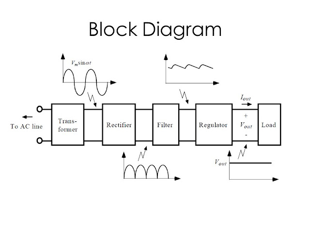
AC-DC Power Supply 1 ( Block Diagram)

Image
  THEORETICAL BLOCK DIAGRAM So the basic purpose of a power supply is to convert and AC signal to DC Signal. The block diagram of the power supply would be something like given below The small electronic circuits cannot handle high voltage current. So a transformer is used to reduce the AC input and will give the required AC voltage value at output Now to convert an AC signal to DC signal A rectifier is used. The output from the rectifier is not a pure DC output. In fact, it contains a lot of ripples and it is highly not smooth. To make the DC output smooth and remove the AC content of the rectifier a filter circuit is used. This filter is either LC (inductor-capacitor) filter, RC (resistive – capacitive) filter. The choice of the filter depends on the designer of the circuit and to the type of power supply. The output now becomes a full DC with constant signal but still it is unregulated voltage. Meaning that a designer is receiving a higher than required voltage. So,

Electronic Devices and Circuits Understanding Diode

Image
 A one of the basic circuit element with numerous applications. Diode is a semiconductor device which allows the flow of current only in one direction and stops the flow of the diode in the opposite direction. Due to this peculiar behaviour of diode it is used in making power supplies especially mobile phone charges and adaptors of laptops and etc. Ideal Diode: An ideal diode is shown in the figure above. An ideal diode behaves as a short circuit when operated in forward direction ( forward biased region) and acts as an open circuit when operated in reverse direction ( reverse biasing region). An ideal diode has zero voltage drop at its terminals. In the figure a above it can be clearly see that when positive terminal of the battery is connected with the positive terminal of the diode. in this case the diode is short circuited and current will flow through the circuit and bulb will glow In figure b negative terminal of the battery is connected is with the positive terminal of the diode

555 Timer IC Details

Image
  Introduction The 555 timer IC is an integrated circuit IC designed by Signetic in 1972. It is used in any circuit where there is a need of time control. As of 2003 about one billion units were manufactured. In the history of ICs it is one of the most popular IC ever made. According to this block diagram of the timer IC, it has 8 pins which perform different functionality. The circuit of timer IC consists of  Resistors Comparator Transistor Flip Flop Output Inverter Circuit Elements: Resistor:  It is a circuit element used in a circuit where there is a need to reduce the flow of the current in the circuit. It's value is measured in Ohms and it the basic circuit element. Following is the circuit element of the resistor Comparator: In electronics, a comparator is a device that compares two voltages or currents and outputs a digital signal indicating which is larger. Given below is the comparator circuit device. Flip Flop: In electronics, a flip-flop or latch is a circuit that has tw

Electrical Engineering Books For Beginners

Image
  Electrical Engineering: Electrical engineering is the branch of engineering which deals with the design and application of the system, equipment and devices which uses electricity, electronics and electromagnetism. The scope of electrical engineering is big because of its different sub-fields like telecommunication, power engineering, satellite engineering, electronics etc.  The basic tools of the electrical engineering or any of its sub-field are circuits.  As the field is quite big. The question here is what type of books should an undergraduate begineer electrical engineering student read ? As I am also an electrical engineering student. I have read all of the following books. And I as a student found out that these following books are one of the good books for an electrical engineering students. Fundamentals Of Electric Circuits: This book is written by Charles k Alexander and Matthew N Sadiku. The reason why I suggest this book is because it contains basic concepts on circuits,